Application Note: Linear Metering Tubes

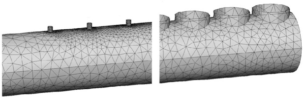
A common engineering design task in many industries and applications is linear gas injection tubes, often referred to as linear metering tubes. These are a type of gas distribution manifold, usually the final element of the gas delivery system, from which gases are delivered into the processing environment and flow across or around the substrates to be processed. With a single inlet point and multitude of outlets—sometimes numbering in the hundreds—these parts are conceptually simple with few critical dimensions. Yet they often embody complex gas flow phenomena that can yield counterintuitive or simply unsatisfactory process results.
The design requirements are usually simple:
-
•Identical gas mass flow rate from each hole.
-
•Identical gas composition from each hole.
In many cases meeting these requirements is no great challenge, and injectors can be designed that meet uniformity requirements with room to spare. But as any engineer will attest, what works for one process will not necessarily work for another by logical extension. For example, changes in injector length, outlet pressure, and process temperature each affect outlet flow uniformity. Increasing the length of a silicon wafer furnace or the width of a lateral gas injector for translating substrates each require extending the length of a linear metering tube. What assumptions is a design engineer to make? Does one simply extend the length of the tube, keeping the outlet hole pitch the same but increasing the number of holes? To keep the flow-per-hole constant, the engineer must add proportionally more flow at the inlet. But this raises the tube internal pressure and can also affect the outlet flow uniformity in different ways depending on the process pressure. In some cases the flow can become imbalanced toward the inlet end and in other cases near the opposite end. Should the tube inside diameter or outlet hole diameters be scaled proportionally? Answers are not always apparent, nor even calculable via dimensional analysis.
All Content Copyright 2011 nVision Engineering LLC. All rights reserved.